How to choose a double-acting hydraulic cylinder — 7 steps
A double-acting hydraulic cylinder delivers force in both directions of motion — oil works alternately on both sides of the piston. Choosing correctly means working through 7 parameters: force and bore (25–200 mm per ISO 6020/2), stroke with a buckling check, working pressure (160–250 bar by series), mounting, seals by medium and temperature, end-of-stroke cushioning and environmental influences. hydraulika.store is an authorised distributor of Conforti Oleodinamica for the Czech Republic and Slovakia with delivery across the EU — typically within 14 days, urgent production from 48 hours, every cylinder is 100% tested per ISO 10100.
Step 1 — Force, bore and series
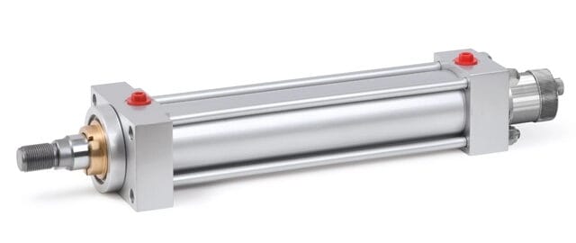
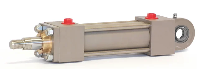
Start from the required force and derive the bore from it (25–200 mm per ISO 6020/2). The force of a linear cylinder is F = p × A — the push area is the whole piston, the pull area is only the annulus reduced by the rod, so the pull (retract) force is always smaller. From the force and the required pressure you also make a preliminary series choice (standard CD/DK 160 bar, flange-mounted HD/HK 210 bar, heavy-duty DP 250 bar) — pressure and the series choice are refined in Step 3.
Example: a Ø 50 mm cylinder at 160 bar → A₁ = 19.63 cm² → F ≈ 31.4 kN push force. With a Ø 28 mm rod the annulus is 13.47 cm² → pull force ≈ 21.6 kN. The retract force is always smaller — bear that in mind if the cylinder pulls a load.
To the theoretical force add the reserves that are commonly forgotten: friction of the guide and mechanisms (10–30 % of the force over the application's life), the forces needed to accelerate the mass, and pressure losses in valves and piping. The recommended pressure reserve is 10–20 %. And take care when synchronising movements: on retraction the effective area is smaller by the rod, so at the same flow the retract stroke is noticeably faster — the difference can be 30 % or more.
Don't feel like calculating? The configurator works out force and flow automatically and immediately checks the compatibility of all choices.
Step 2 — Stroke and piston-rod buckling check
According to Conforti Oleodinamica, under-sizing the piston rod is the single most critical selection error. Under a compressive load and a long stroke the rod behaves like a strut in buckling (Euler theory): once the critical length-to-diameter ratio is exceeded, it bends. The consequences: damaged guide bushings, destroyed seals and, in extreme cases, a broken rod.
The most common selection error: an under-sized piston rod. Always verify buckling against the catalogue bore/rod ratio tables — not by estimating from the force. Add the length of the spacer ring to the stroke.
Practical rules:
- Stick to the catalogue bore/rod ratio tables per ISO 6020/2 — for each bore Conforti offers up to 3 rod diameters.
- Specify the stroke to the millimetre; the stroke tolerance per ISO 8131 is 0/+2 mm (never less than the nominal value).
- Watch out for minimum strokes: on the CD/DK series the limit applies only to the H mounting (intermediate trunnions, ISO MT4) — e.g. Ø 25 → min. 5 mm, Ø 63 → 25 mm, Ø 200 → 75 mm. On the MD series (magnetic sensors) all mountings have minimum strokes because of the space needed for the sensors.
- Stroke over 2,000 mm: choose the front-flange series HD/HK — there is no tie-rod stretching under load — and consider bushing drainage (option SD), which returns excess fluid between the scraper and the seal back to the tank.
- Spacer ring: on long strokes it reduces the load on the guide; the catalogue prescribes it by stroke band — note that the ring length is added to the stroke for the buckling calculation. The bands differ by standard: the more robust DP/TP series (ISO 6022) adds the ring only from longer strokes than the ISO 6020/2 series.
| Stroke | Spacer |
|---|---|
| 0–1 000 mm | - |
| 1 000–1 500 mm | SJ 50 |
| 1 500–2 000 mm | SJ 100 |
| 2 000–3 000 mm | SJ 150 |
| 3 000–4 000 mm | SJ 200 |
| Stroke | Spacer |
|---|---|
| 0–1 500 mm | - |
| 1 500–2 000 mm | SJ 50 |
| 2 000–3 000 mm | SJ 100 |
| 3 000–6 000 mm | SJ 150 |
How to verify buckling from the catalogue graph: the mounting determines the stroke factor FC; multiplying the stroke CO by the factor FC gives the ideal length LI. Read the LI value on the vertical axis, intersect it with the curve for the given rod diameter and read off the maximum possible push force on the horizontal axis. If the actual force does not exceed it, the check is satisfied. Spacer rings and rod extensions are added to the stroke (CO). Where impacts and impulse forces cannot be avoided, choose the heavy-duty PQ piston combined with a hardened and tempered rod.
Step 3 — Working pressure and series selection
| Conforti series | Standard | Nominal pressure | Bores | Tested (ISO 10100) |
|---|---|---|---|---|
| CD / DK (tie-rods) | ISO 6020/2 | 160 bar | 25–200 mm | 240 bar |
| HD / HK (counter-flanges) | ISO 6020/2 dimensions | 210 bar | 50–200 mm | 315 bar |
| DP (heavy duty) | ISO 6022 | 250 bar | 50–200 mm | 375 bar |
| RP / MP (compact) | — | 160 bar (Ø 25–63) · 100 bar (Ø 80–100) | 25–100 mm | — |
| RQ (compact steel) | — | 250 bar | 25–100 mm | — |
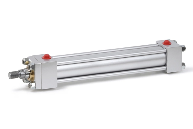
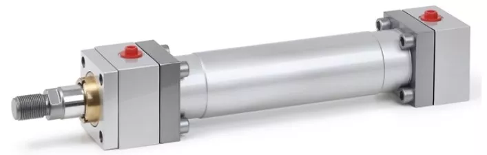
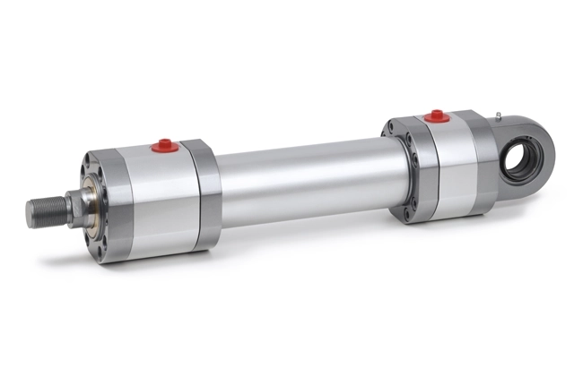
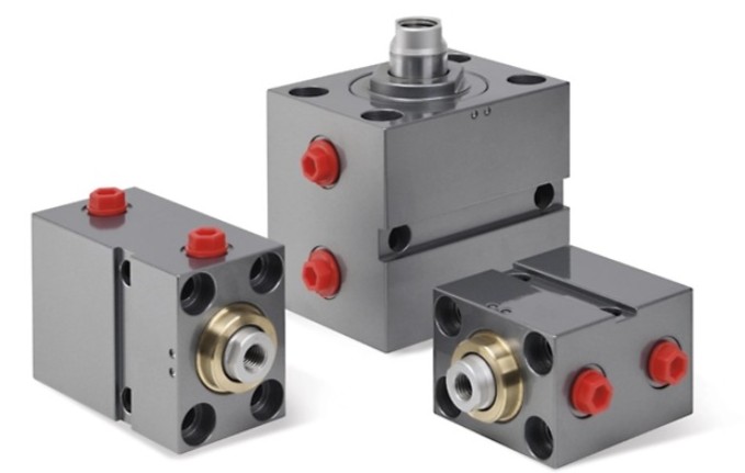
Choose the pressure by the peak in the circuit (start-ups, shocks, water hammer), not by the pump's nominal pressure. Every Conforti cylinder undergoes a 100% pressure test at 1.5 times the working pressure — not a random batch check.
Step 4 — Mounting and radial forces
The mounting determines how the cylinder transfers forces into the machine frame. For tie-rod cylinders ISO 6020/2 defines a complete range: flanges, foot mounts, trunnions (front, rear, intermediate), eyes and clevises — 14 variants at Conforti. A poor choice is the main source of radial forces, which prematurely destroy the guide bushing and the rod seals:
- an overly "constrained" mounting with no degrees of freedom generates unpredictable reactions,
- misalignment between the cylinder and the load guide,
- the cylinder's own weight in horizontal mounting with a long stroke (the centre of gravity shifts significantly between the retracted and extended positions).

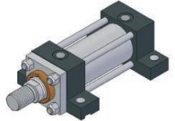


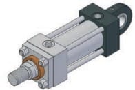
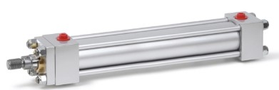
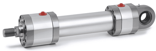
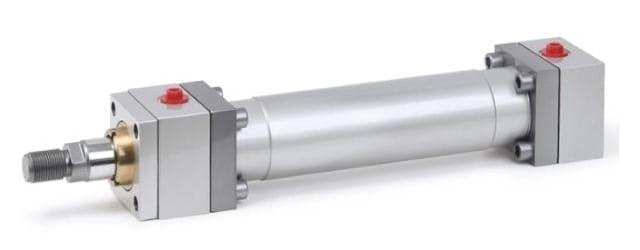
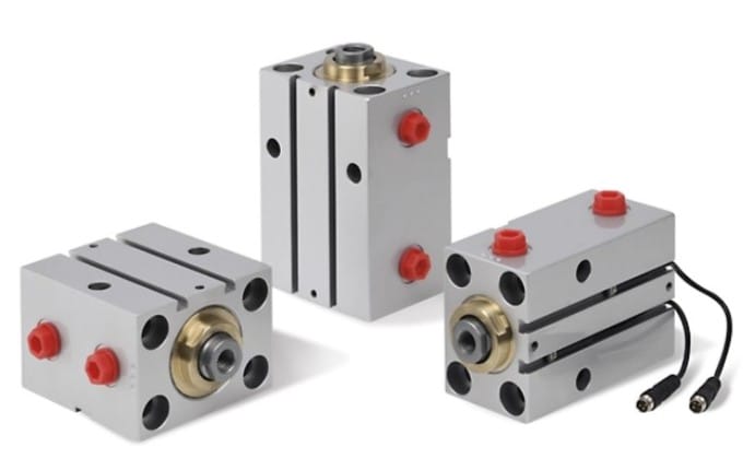
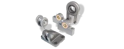
Six of the 14 mounting variants per ISO 6020/2 (photographs of actual Conforti mountings). Choose pivoting mountings (eyes, trunnions) where the direction of force changes.
The solution: pivoting mountings (eyes, trunnions) where the direction of force changes; on long strokes a spacer ring that lengthens the internal arm between the bushing and the piston; under sustained radial loads go straight for the DP series per ISO 6022 with double bronze piston guiding and a long bronze rod bushing.
Step 5 — Seals by medium, temperature and speed
| Code | Material | Max. speed | Temperature | Medium |
|---|---|---|---|---|
| S — high-seal | NBR + PTFE | 0.5 m/s | −20 / +80 °C | mineral oil |
| L — low friction | NBR + PTFE | 1 m/s | −20 / +80 °C | mineral oil |
| H — Viton® | FKM + PTFE | 1 m/s | up to +150 °C | high temperatures, phosphate esters |
| G — HFC | special | 1 m/s | by medium | water-glycol |
The principle: never "standard seals" without analysing the conditions. Ask about the fluid type, the temperature range and the rod speed — speeds above 0.5 m/s require a low-friction PTFE version. Conforti's seal grooves match the ISO dimensions. It pays to order the seal set together with the cylinder; for later maintenance and servicing we supply seal sets as well as individual cylinder components (KITs, front flanges, piston rods, piston and more) as a spare part — see spare parts and accessories.
Step 6 — Cushioning, venting and position sensing
- End-of-stroke cushioning: codes V (front), Z (rear), K (both). Adjustable cushioning protects the structure at higher speeds and frequent cycles; a floating cushioning ring ensures a quick start of the return movement.
- Venting: codes SV / SZ / SK (front / rear / both). On cylinders with cushioning, the cushioning adjusting screw can be used for venting.
- Cushioning adjustment (SGF): cushioned cylinders have an adjusting screw — slightly loosen the Seal-Lock® sealing nut, adjust with the screw and carefully re-tighten; the same screw also serves for venting (loosen the nut until air escapes). If the stroke is shorter than the cushioning length, the cylinder cushions over the whole stroke.
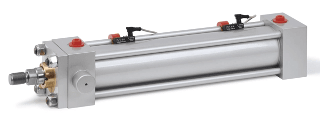
- Position sensing: end-of-stroke positions are handled by magnetic sensors on the MD series — the cylinder has an integrated magnet, and SR sensors (REED contact, 3–110 V AC/DC) or SH sensors (electronic PNP output, 6–30 V DC) are ordered together with a mounting clamp by bore (STA Ø25–40, STB Ø50–63, STC Ø80–100, STD Ø125). Continuous measurement is provided by magnetostrictive transducers in servo cylinders (TD/TK/TH/TX/TP). If you plan inductive SPV/SPZ/SPK proximity switches, allow for the corresponding cushioning direction (SPK requires K cushioning). The article Hydraulic cylinder position sensors describes in detail which sensor goes on which cylinder and how to add it to an inquiry.
Step 7 — Environment: corrosion, abrasives, washdown
- Corrosion / moisture / chemicals: a chrome-plated stainless piston rod (RRX) + electroless nickel plating of the body NK (20 µm, 1,200 h salt spray) — often cheaper and faster than an all-stainless cylinder. Details in the article on NK nickel-plated cylinders.
- Rod material by loading: standard chrome-plated CK45; for corrosion chrome-plated stainless (RRX); for impacts hardened and tempered chrome-plated steel (RRB); Nichrome (RRK); hardened chrome-plated steel (RRH). Always ground and chrome-plated — for low friction and long seal life.
- Dust, chips, abrasives (foundries, stone, material cutting): a metal RM scraper that wipes off even particles that an elastomer scraper lets through.
- High cycle rates: heat in the oil rises — bear H seals and temperature monitoring in mind.
Document the minimum/maximum temperatures, aggressive substances, dust levels and cycle frequency — without this the cylinder cannot be correctly specified.
A real-world example: one application, two different configurations
What do the 7 steps look like on a real order? An engineering customer requested cylinders for their application; after a phone consultation that filled in the application parameters, and a technical review directly with the manufacturer, two configurations emerged:
HD SX 50/36 G K 2750 SJ150 H SK SD — the long 2,750 mm stroke decided on the HD series with counter-flanges (step 2: no tie-rod stretching). The rest follows from the catalogue rules: spacer ring SJ 150 (stroke band 2,000–3,000 mm), bushing drainage SD (for a stroke over 2,000 mm and at the same time higher speeds — both conditions must hold), cushioning in both positions (K) to limit impact in the end-of-stroke positions with SK venting (front and rear), Viton® H seals because of the medium temperature, and front-trunnion mounting (G) with a pair of LK brackets. The SX code denotes a special version.
CD SX 50/36 D K 950 S SK SPK — the second movement, with a 950 mm stroke, is handled by the standard CD series: a stroke up to 1,000 mm needs no spacer, the spherical rod eye (D) deals with the change in the direction of force, and inductive end-of-stroke proximity switches in both directions (SPK) required K cushioning per the rule. High-seal seals S, SK venting.
For both configurations the customer received 3D CAD models — including a model of the accessory, the CS 272 rod eye — so they verified the dimensional fit in the assembly before ordering. This is exactly the difference between "buying a cylinder" and "choosing a cylinder": every letter of the code is backed by a catalogue rule.
The result: an unambiguous order code
Working through all 7 steps produces a configuration that can be written as a single code — e.g. CD 32/14 A 500 S: a cylinder per ISO 6020/2, bore Ø 32 mm, piston rod Ø 14 mm, mounting A, stroke 500 mm, high-seal seals S, working pressure 160 bar. Such a code eliminates communication errors in both the inquiry and the order.
The online configurator works through all 7 steps for you: it asks about the application (not about series codes), checks for incompatibilities, builds the code and generates the datasheet — the same philosophy as the CAD configurator by the manufacturer Conforti, which delivers 2D/3D models within minutes. You put the result straight into an inquiry. The technical catalogues for all series and a glossary of terms can be found in the TechHub.
The 5 most common selection errors
According to the statistics, the most common cause of cylinder failure is a poor selection, not a manufacturing defect. Most people make these five errors during selection — yet each has a simple solution (referring to the steps above):
- Under-sized piston rod (buckling). Only the force is calculated, buckling on a long stroke is forgotten → damage to bushings, seals and, in extreme cases, breakage. Solution: catalogue bore/rod ratio tables per ISO 6020/2, not an estimate.
- Force without reserves. F = p × A alone is not enough — friction of the guide and mechanisms takes away 10–30 % of the force; add the force to accelerate the mass, pressure losses in valves/piping and a safety factor. Solution: a pressure reserve of 10–20 %.
- Unsuitable seals. "Standard" seals regardless of medium, temperature and speed. NBR+PTFE up to +80 °C, Viton up to +150 °C, speed above 0.5 m/s → low-friction PTFE. Solution: selection by medium/temperature/speed + a spare seal set ordered in advance.
- Overlooked radial forces. Rigid mountings with no degrees of freedom, misalignment, own weight on long strokes. Solution: pivoting mountings, a spacer ring, bronze bushings, and for a sustained side load the DP series per ISO 6022.
- Ignored environment. A standard cylinder fails quickly in corrosion, dust or heat. Solution: nickel plating/stainless, a metal scraper, bellows, seals by temperature and preventive maintenance according to the severity of operation.
Frequently asked questions
Tap a question — the answer appears below. Verified against Conforti Oleodinamica's technical documentation.
Verified against
- Conforti Oleodinamica catalogues (Catalogo_EN, DP_EN, HD_HK_EN, MP_RP_RQ_EN) — series, pressures, seals, spacer, minimum strokes, code composition.
- Conforti Oleodinamica — PLUS: cylinder selection, ISO 10100 testing, fast production, custom cylinders.
- Cylinder series catalogues and technical library: TechHub.
Viton® is a trademark of The Chemours Company. The name is given solely to identify the seal material per the catalogue of the manufacturer Conforti Oleodinamica.